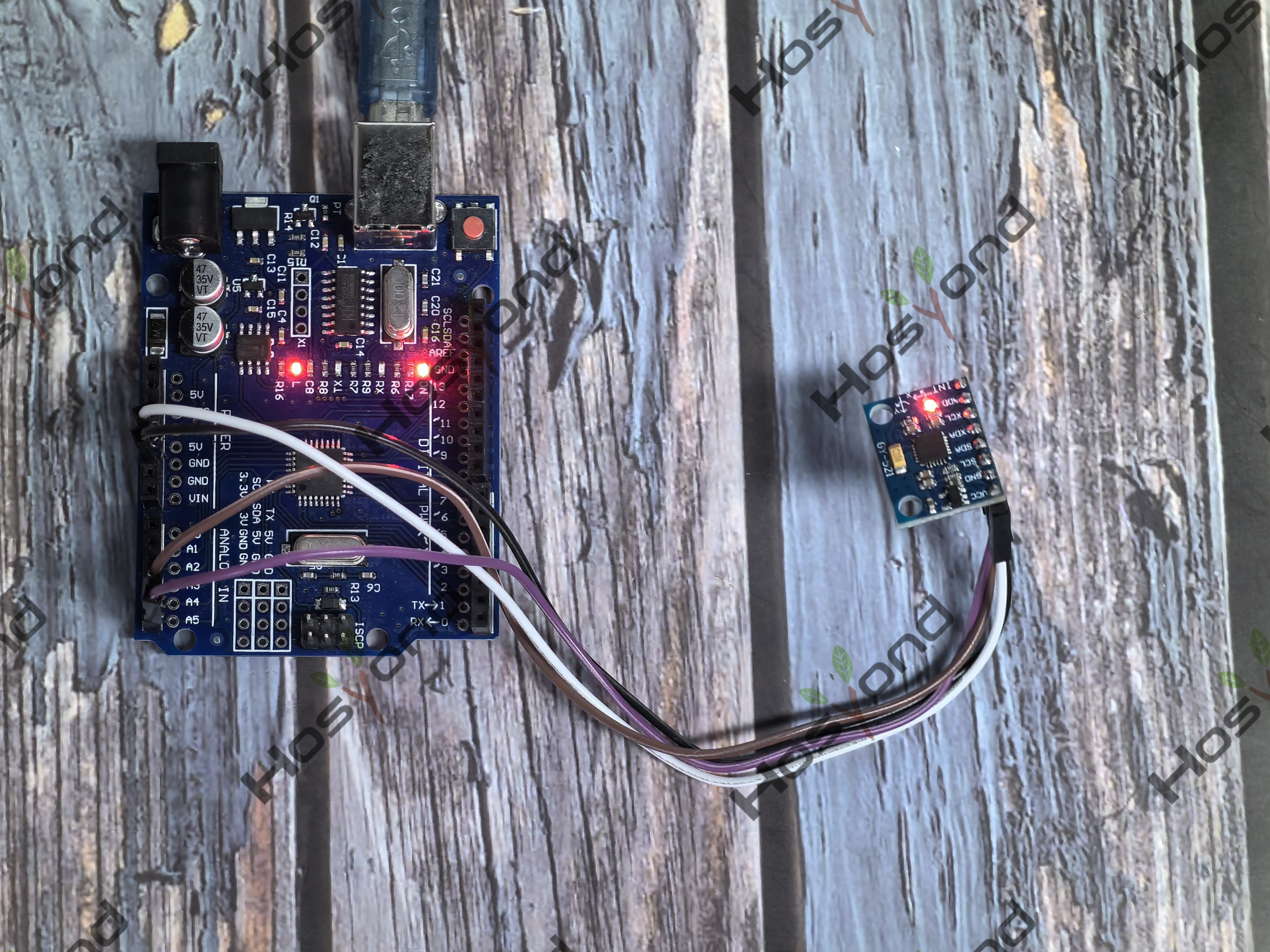
Project40.GY521 Module
Description
The GY-521 module features a 3-axis gyroscope, a 3-axis accelerometer, a digital motion processor (DMP), and a temperature sensor.The digital motion processor can be used to process complex algorithms directly on the board.
Specification
Chip Used: MPU-6050
Power Supply: 3-5V (internal low-dropout voltage regulator)
Communication Method: Standard I2C communication protocol
Built-in 16-bit AD converter, 16-bit data output
Gyroscope Range: ±250, ±500, ±1000, ±2000 °/s
Accelerometer Range: ±2, ±4, ±8, ±16g
Connect
GY-521 |
Arduino |
VCC |
5V |
GND |
GND |
SCL |
Pin A5 |
SDA |
Pin A4 |

Code
#include "Wire.h" // This library allows you to communicate with I2C devices.

const int MPU_ADDR = 0x68; // I2C address of the MPU-6050. If AD0 pin is set to HIGH, the I2C address will be 0x69.

int16_t accelerometer_x, accelerometer_y, accelerometer_z; // variables for accelerometer raw data
int16_t gyro_x, gyro_y, gyro_z; // variables for gyro raw data
int16_t temperature; // variables for temperature data

char tmp_str[7]; // temporary variable used in convert function

char* convert_int16_to_str(int16_t i) { // converts int16 to string. Moreover, resulting strings will have the same length in the debug monitor.
sprintf(tmp_str, "%6d", i);
return tmp_str;
}

void setup() {
Serial.begin(9600);
Wire.begin();
Wire.beginTransmission(MPU_ADDR); // Begins a transmission to the I2C slave (GY-521 board)
Wire.write(0x6B); // PWR_MGMT_1 register
Wire.write(0); // set to zero (wakes up the MPU-6050)
Wire.endTransmission(true);
}
void loop() {
Wire.beginTransmission(MPU_ADDR);
Wire.write(0x3B); // starting with register 0x3B (ACCEL_XOUT_H) [MPU-6000 and MPU-6050 Register Map and Descriptions Revision 4.2, p.40]
Wire.endTransmission(false); // the parameter indicates that the Arduino will send a restart. As a result, the connection is kept active.
Wire.requestFrom(MPU_ADDR, 7*2, true); // request a total of 7*2=14 registers

// "Wire.read()<<8 | Wire.read();" means two registers are read and stored in the same variable
accelerometer_x = Wire.read()<<8 | Wire.read(); // reading registers: 0x3B (ACCEL_XOUT_H) and 0x3C (ACCEL_XOUT_L)
accelerometer_y = Wire.read()<<8 | Wire.read(); // reading registers: 0x3D (ACCEL_YOUT_H) and 0x3E (ACCEL_YOUT_L)
accelerometer_z = Wire.read()<<8 | Wire.read(); // reading registers: 0x3F (ACCEL_ZOUT_H) and 0x40 (ACCEL_ZOUT_L)
gyro_x = Wire.read()<<8 | Wire.read(); // reading registers: 0x43 (GYRO_XOUT_H) and 0x44 (GYRO_XOUT_L)
gyro_y = Wire.read()<<8 | Wire.read(); // reading registers: 0x45 (GYRO_YOUT_H) and 0x46 (GYRO_YOUT_L)
gyro_z = Wire.read()<<8 | Wire.read(); // reading registers: 0x47 (GYRO_ZOUT_H) and 0x48 (GYRO_ZOUT_L)

// print out data
Serial.print("aX = "); Serial.print(convert_int16_to_str(accelerometer_x));
Serial.print(" | aY = "); Serial.print(convert_int16_to_str(accelerometer_y));
Serial.print(" | aZ = "); Serial.print(convert_int16_to_str(accelerometer_z));
// the following equation was taken from the documentation [MPU-6000/MPU-6050 Register Map and Description, p.30]
Serial.print(" | gX = "); Serial.print(convert_int16_to_str(gyro_x));
Serial.print(" | gY = "); Serial.print(convert_int16_to_str(gyro_y));
Serial.print(" | gZ = "); Serial.print(convert_int16_to_str(gyro_z));
Serial.println();

// delay
delay(500);
}
Phenomenon