Project29.Infrared Obstacle Avoidance Sensor Module
Description
The module has a pair of infrared LEDs, an emitter, and a receiver. The emitting LED sends infrared light pulses at a certain frequency. When the light hits an obstacle is reflected back to the receiver LED.
The KY-032 has 4 pins: GND, +, S (out), and EN. The jumper makes the module permanently enabled so it’s always detecting for obstacles. To control the state of the sensor remove the jumper and use the EN pin, a HIGH signal will enable the sensor and a LOW signal will disable it.
You can adjust the detection distance by turning the left knob, turn it to the middle for maximum distance. The right knob controls the frequency of the emitting IR pulse, turn it clockwise all the way to set the emitter to the right frequency required to work with the receiver.
Specification
Working voltage 3.3V – 5V DC
Working current ≥ 20mA
Working temperature -10°C – 50°C
Detection distance 2cm – 40cm
IO interface 4-wire interface (/EN/+/S/-)
Output signal TTL level (low level if obstacle detected, high if no obstacle)
Adjustment method multi-turn resistance adjustment
Effective angle 35°
Board Size 1.6cm x 4cm [0.62in x 1.57in]
Weight 9g
Connect
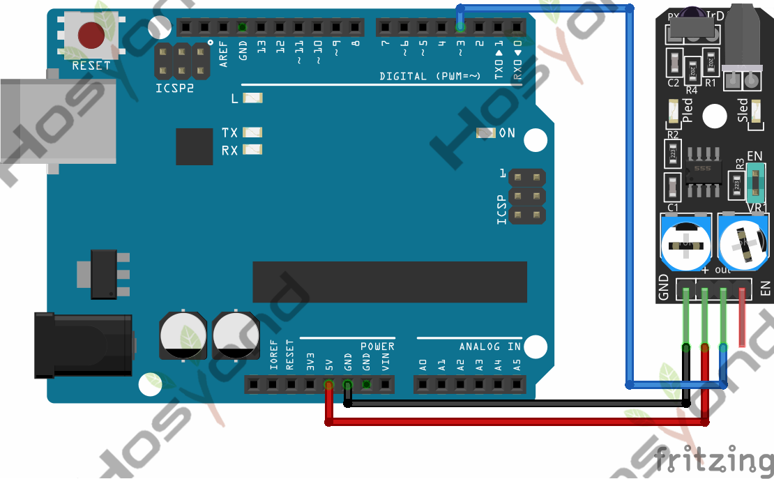
Code
int ledPin = 13;      // LED pin on arduino
int detectorPin = 3;  // obstacle avoidance sensor interface
int val;              // variable to store result
//int enablePin = 2;  // sensor enable interface (EN)

void setup()
{
pinMode(ledPin, OUTPUT);  // Define LED as output interface
pinMode(detectorPin, INPUT);  // Define obstacle avoidance sensor as input interface

// [uncomment and remove jumper on module to use enable pin (EN)]
//pinMode(enablePin, OUTPUT);
//digitalWrite(enablePin, HIGH);  // Enable sensor
}

void loop()
{
val = digitalRead(detectorPin); // Read value from sensor
if(val == LOW) // When the sensor detects an obstacle, the LED on the Arduino lights up
{
    digitalWrite(ledPin, HIGH);
}
else
{
    digitalWrite(ledPin, LOW);
}
}
Phenomenon
